Antenna System Solutions
- MACRO BASE STATION GREEN ANTENNA
- IBS ANTENNA
INTRODUCTION TO THE PLAN
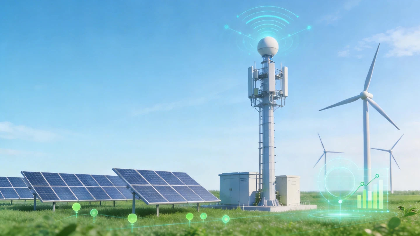
The green antenna solution for Macro Base stations is A key direction that operators and equipment manufacturers are promoting in the current 4G/5G era. It mainly targets the high energy consumption problem of macro base stations (the main base stations with wide coverage), and achieves energy conservation and carbon reduction, efficiency improvement and cost reduction, as well as simplified deployment through antenna innovation. Under the pressure of the "dual carbon" goals and the operational costs of operators, green antennas have become a standard feature for 5G network upgrades, especially performing outstandingly in large-scale replacements and new constructions from 2024 to 2026.
CORE GOALS AND VALUES:
• Energy conservation and carbon reduction: By reducing antenna feed losses and enhancing radiation efficiency, a single antenna can save over 1,800 kilowatt-hours of electricity annually and reduce carbon emissions by approximately 1.69 tons (pilot data). Large-scale deployment can save tens of millions of kilowatt-hours of electricity and reduce carbon emissions by over 10,000 tons per 10,000 stations annually.
• Quality improvement and efficiency enhancement: The coverage range is increased by 1-3dB (equivalent to a 25%-30% expansion of coverage), the spectrum utilization rate is raised by approximately 15%, and it supports multi-frequency and multi-standard integration (4G/5G co-construction and sharing).
• Simplified deployment: Miniaturization, lightweight, multi-system shared antenna, reducing antenna occupation, no need to add new antennas, and supporting rapid replacement of existing ones.
• Environmental protection process: Low-loss materials are adopted, electroplated or non-electroplated processes are used, and recyclable antenna covers are utilized to reduce production pollution and waste

SCHEME ARCHITECTURE
Centering on the core goals of 'low loss, high efficiency, environmental friendliness and multi-frequency integration', a comprehensive reconstruction is carried out on the traditional antenna feeding, radiation, materials and integration methods. The traditional macro base station antenna architecture relies on long feeder cables (with high feed loss, heavy weight, and complex installation), while the green solution eliminates or minimizes these pain points through innovative design, achieving an energy conversion efficiency improvement of over 20%, power conservation and carbon reduction, and simplified deployment.

INTRODUCTION TO CORE PRODUCTS
-
HPT-DA-10P-0727-65R17-E
Learn More- 1*698-960/4*1710-2690MHz
- 1L4M 10-Port
- 10 x 4.3-10 Female
- Each Band Individually Adjustable
-
HPT-DA-10P-0738-65R17-E
Learn More- 1*698-960/2*1695-2690/2*3300-3800 MHz
- 10-Port 4.3/10(F) 1L2M2H
- Each Band Individually Adjustable
-
HPT-DA-12P-0721-6533R18-E
Learn More- 4*694-960/8*1695-2180MHz
- 1695-2180MHz Twin-beam
- 12 x 4.3-10 Female
- Each Band Individually Adjustable
-
HPT-DA-12P-1721-15R20
Learn More- 12*1695-2180MHz
- Multibeam Antenna 6*15°HPBW
- 12 x 4.3-10 Female
- Each Band Individually Adjustable
APPLICATION SCENARIOS
-
DEPLOYMENT CASE OFGREEN ANTENNA PARK
Green and highly efficient antennas have been deployed in the Bay Park
-
DEPLOYMENT CASE OFGREEN ANTENNA RESORT
Green and efficient antennas have been deployed at the manor resort
-
GREEN ANTENNA OFFICEPARK DEPLOYMENT CASE
Green and efficient antennas have been deployed in office buildings
INTRODUCTION TO THE PLAN
This solution offers a comprehensive range of indoor coverage antennas, enabling operators, system integrators, and enterprises to rapidly deploy high-performance Indoor Distributed Antenna Systems (DAS). It addresses full-scenario coverage requirements across 2G, 3G, 4G, and 5G networks, adapting to diverse indoor environments and effectively resolving signal coverage pain points.

SCHEME ARCHITECTURE
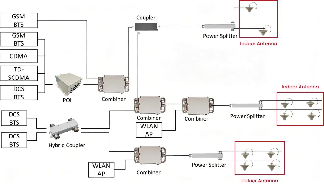
Within an Indoor Distributed Antenna System (DAS), indoor antennas serve as the final output terminals for RF signals, directly determining coverage quality and user experience. Connected via feeder cables to upstream passive components—such as power splitters and couplers—these antennas radiate the distributed RF energy into target areas, either uniformly or directionally.
The entire antenna layer operates independently of the signal source and combining units; provided it is properly matched with the front-end equipment, it can be flexibly integrated into both existing and newly constructed indoor coverage systems.

INTRODUCTION TO CORE PRODUCTS
-
Log-periodic antenna
Learn More- 698-960/1710-2700/3300-3800MHz
- Easy installation
- Ultra wide band
- Size:440*210*65mm
-
Omni Antenna MIMO
Learn More- 698-960/1710-2700/3300-3800MHz
- Easy installation
- Ultra wide band
- Size 220*24mm
-
Omni Antenna SISO
Learn More- 698-960/1710-2700/3300-3800MHz
- Easy installation
- Ultra wide band
- Size 186*86mm
-
Panel Antenna MIMO
Learn More- 698-960/1710-2700/3300-3800MHz
- Easy installation
- Ultra wide band
- Size 307*192*68mm
APPLICATION SCENARIOS
-
COMMERCIAL COMPLEXES
Omni antennas are deployed in open areas, while panel antennas are utilized in corridors and private rooms to meet the communication demands of high-traffic customer flows.
-
OFFICE BUILDINGS/HOTELS
Omni antennas provide coverage for lobbies and conference rooms, while panel antennas are deployed in corridors and elevator halls to ensure network stability.
-
PARKING LOTS
Panel antennas serve as the primary solution for long, narrow lanes, while omni antennas supplement coverage in open areas, thereby eliminating signal blind spots.